

BE3 Gearbox Stripdown

Removing the Speedo Drive
I removed the speedo drive housing to allow the gearbox to sit on the bench rather better than it would if it had remained in place. It is not strictly necessary to do this but it'll make everything a little easier!
Slacken and remove the 3 13mm bolts holding the drive housing to the final drive
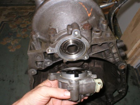
Pull it gently forward and recover the "O" ring seal and speedo drive gear.
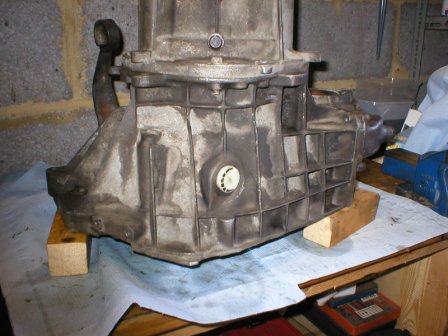
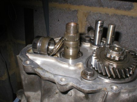
Putting the 'box on the bench ready for the main strip
Even with the speedo drive removed, the 'box will not sit directly on the bench as the input shaft extends beyond the end of the bellhousing and there are dowels present. Place three blocks on the bench and place the gearbox bellhousing-down on the blocks as shown below.
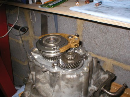
Removing the 5th gear pinions, synchro hub and selector fork
Remove the end cover (11mm bolts plus the 19mm fill/level plug) to expose the 5th gear components.
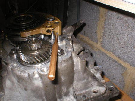
Using an appropriate pin-punch, drive out the roll-pin securing the 5th gear selector fork to the 5th gear selector rod. Recover the pin.
Push the selector fork downward to engage 5th gear. Remove the circlip at the top of the detent rod. Recover the circlip.
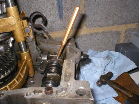
With 5th gear still engaged, use the "hockey" stick gear selection lever to select any other gear. Simply turn the lever either clockwise or anti-clockwise until you feel the gear engage. This will have the effect of locking the gearbox up solid by selecting two gears at once, which is necessary for removing the bi-hex nuts securing the 5th gear pinions to the input and output shafts.
Relieve the staking on the nuts and using the 5/8" Whit socket, undo the nut above the 5th gear synchro hub.
Lift the nut and inner gear below it as shown above.
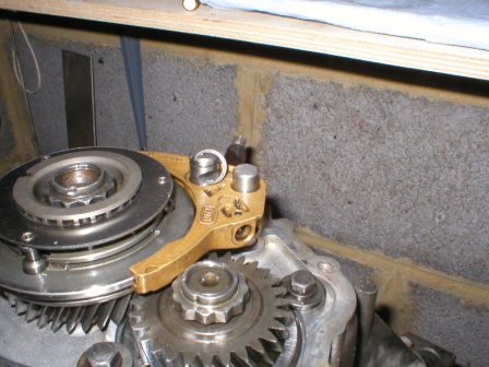
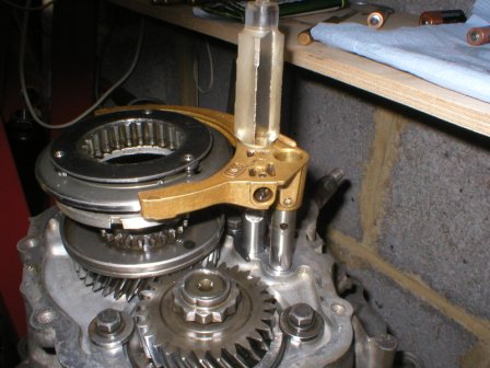
It is now necessary to remove the 5th gear synchro hub and selector fork. There is a very strong spring and detent ball in the selector and a special tool is employed to retain this ball and spring as the fork is removed. I turned up a length of plastic rod to the same diameter as the detent rod (15mm). Place the tool on top of the shaft and carefull pull the selector fork and hub up, being aware that you will feel two strong detents. Allow the tool to enter the fork as it comes up, thereby retaining the detent ball and spring.
Replace the 5th gear hub components temporarily to allow the bi-hex nut on the output shaft to be undone.
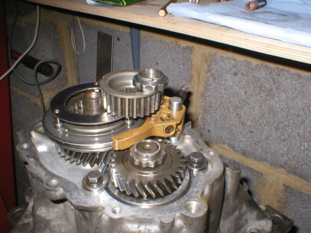
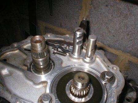
Remove the 5th gear hub and related components, noting the orientation of the stepped washer above the bearing.
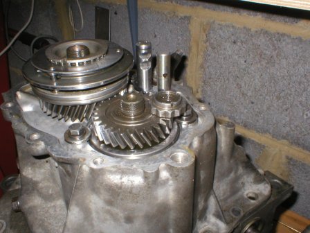
Remove the 5th gear pinion from the output shaft. This is not strictly necessary but makes life easier.
Remove the locking tab from the 1st-4th gear selector rod.
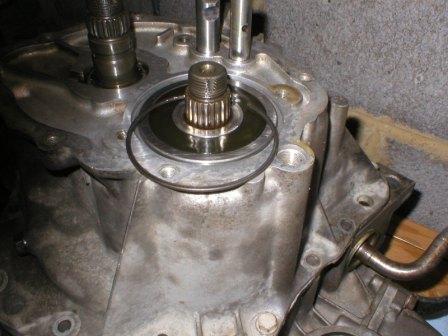
Remove the output shaft bearing retainer studs and washers.
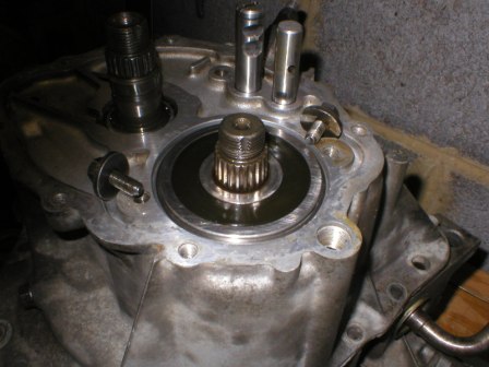
Carefully remove the output shaft bearing retaining circlip using a small screwdriver and scriber or other pointed instrument. It will be necessary to lift the output shaft slightly to allow the clip to pop pout.
Removing the 1st-4th gear cluster case
In order to gain access to the main gear cluster, it is necessary to remove the gear case.
Remove the reverse gear idler shaft securing bolt.
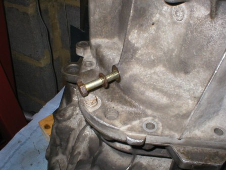
Undo all the case bolts (11mm) and gently tap around the bottom to release the gasket seal. DO NOT lever on the mating faces else serious damage will result. No actual gaskets are used anywhere in the gearbox and oil tightness is assured only by accurate machined surfaces and a thin smear of sealant.
By pressing on the input and output shafts and the gear selector rods, gently ease the cover up and over the cluster. Put the cover somewhere safe to avoid damage to the mating faces.
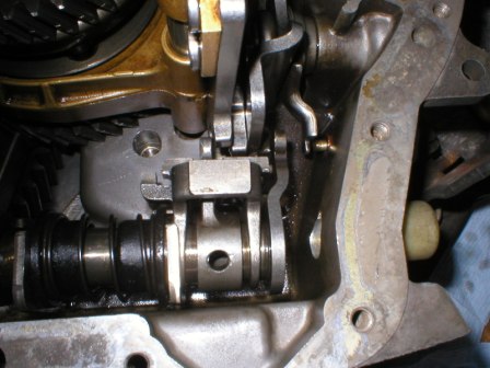
Remove the reverse idler pinion and shaft by carefully lifting up and out. This may fall out of place as the cover is lifted.
Remove the 5th gear selector rod
Removing the gear clusters
Before the gear clusters may be removed, it is necessary to free the gear selector mechanism to give room to disengage the gear selector gate and interlocks from the selector rods.
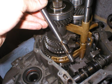
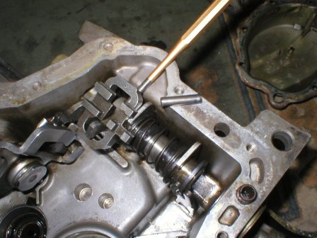
Drive out the inner and outer roll-pins securing the gear selector cranks to the gear selector lever. Note that the pins will not drive fully out at this stage. To ensure they are out far enough to enable the gear selector shaft to be withdrawn, drive at an angle as shown in the second picture.
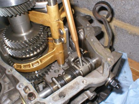
Withdraw the gear selector shaft
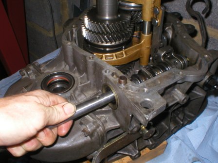
Twist and pull the gear selector gate/interlock mechanism until the "ears" on the ends of the selector fork rods are sufficiently clear to allow the two clusters and rods to be lifted straight up.
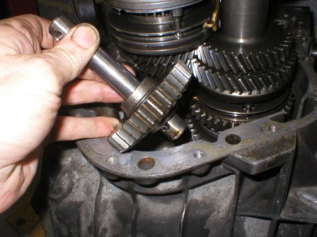
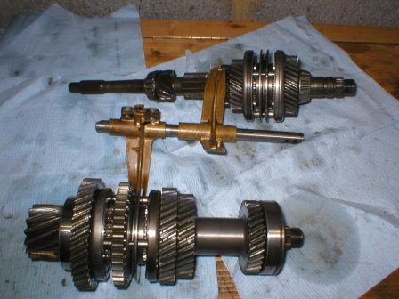
Lift the gear clusters out complete with the selector forks and rods. It will be necessary to carefully rotate the output shaft a little to allow the pinion to clear the crownwheel.
Beware that the cluster is heavy and that the gear teeth are extremely hard and easily chipped. Lay the cluster somewhere clean and safe.
Recover and clean the swarf magnet
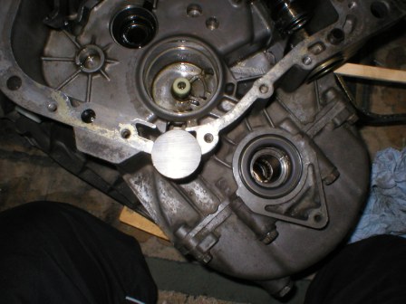
Recover the roll-pins from the selector gate mechanism.
That completes the basic strip.
The next section deals with dismantling the input shaft to replace the 3rd/4th gear synchro cone
Continues next page...
Page last updated 04 August 2007